Learn how to convert your GC carrier gas from helium to hydrogen with this step by step guide.
With recent increases in helium pricing and an increasing number of regulated methods allowing the use of hydrogen as a carrier gas for GC, more labs are looking to switch to alternative carrier gases. This step by step guide will provide you with the necessary information to convert your GC’s carrier gas supply from helium to hydrogen. Hydrogen produced by a gas generator offers a safe, consistent and reliable source of gas as well as being a more convenient and greener source of hydrogen than cylinders.
Once you are satisfied that your method allows for conversion from helium to an alternative carrier gas, follow the steps in this guide to quickly get up and running with an alternative carrier gas while avoiding some of the common pitfalls of switching carrier gas. If you are unsure if your particular method allows for conversion from helium carrier gas, contact us and we may be able to advise you.
Step 1. Review all current method information and instrument conditions
1. Review all methods that are run on the GC in the software and make hard copies.
2. Leak-check the GC to ensure that the flow rates in the method will be achieved when running your analysis.
3. Measure all flow rates indicated in your method (septum purge flow, split flow, carrier gas, and detector gases (if applicable), to ensure that the GC is meeting all setpoints correctly.
4. Keep a note of the linear velocity of your carrier gas.
5. Run a sample and monitor the system to ensure that flows are stable. If any flows change, make a note of these.
6. Keep a record of a good chromatogram to compare with results after changing carrier gas.
Example:
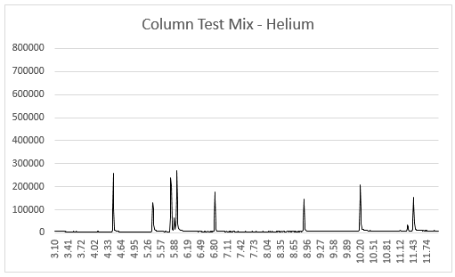 Reference Chromatogram
Step 2. Perform routine GC maintenance before switching carrier gas
1. Change the inlet septum. Use a low bleed septum that is recommended for your GC system.
2. Change the liner. A tapered liner can improve results with hydrogen carrier gas for GC analysis. If you are not using a tapered liner, it may be advisable to purchase some tapered liners before setting up the system.
3. If you are using gas purifiers, it may be advisable to switch these for new ones, depending on how old they are.
4. If you are using a GC-MS and the ion source requires cleaning, this would be a good time to carry this out. Hydrogen carrier gas should maintain the condition of the ion source for longer than helium, so once you have switched carrier gas, you should find that ion source cleaning is required less regularly than before.
5. It is possible to use the same column, provided it is still in good condition. Details are given below regarding conditioning a new column with hydrogen carrier gas.
Step 3. Install new tubing
1. Tubing that was used to supply helium should be discarded. If you use the same tubing to supply hydrogen, you will see high background and it will take longer to optimise your analysis. If you are switching to nitrogen in place of helium for make-up gas, it is also advisable to change this tubing.
2. Within 3m (10 feet) of the application, 1/8” laboratory grade copper or stainless steel tubing should be used. If you are piping gas from a distance greater than 3m, it may be necessary to use ¼” tubing and reduce to 1/8” at each GC. If you are unsure, Peak Scientific can assist you regarding your setup requirements.
3. If you are supplying a GC-MS, you will need to connect just 1 line between the Hydrogen generator and the GC.
4. All fittings should be compression fittings. DO NOT USE SEALING AGENTS or WELD CONNECTIONS. These can introduce volatile organic compounds (VOCs) into the gas stream and contaminate your system.
If you are connecting a GC-FID, you can supply both the carrier gas and fuel gas supply from a single generator. To connect to both gas inlets, prepare a T connection between the carrier and fuel inlets with a single supply line running from the generator. If you are unsure, please contact Peak Scientific for advice on how to connect the generator to your application.
Step 4. Gas supply to GC
The gas generators being used to supply your GC should be installed according to site preparation advice from the manufacturer.
Ensure that the connections into the GC are leak-free using an electronic leak detector – DO NOT USE LIQUID LEAK DETECTORS since these can cause contamination of your gas lines.
Detector gas supply:
1. If your detector requires hydrogen, start the generator and ensure that all connections between the generator and GC are leak-free.
2. If your detector requires nitrogen make-up gas, check that this line is also leak-free by checking before switching on the GC.
3. If your detector requires an air supply, check that this line is also leak-free by checking before switching on the GC.
4. Switch on the GC, making sure that the inlet gas flows are off and check that the detector signal stabilizes.
Carrier gas supply
1. If you are using the column that was already installed, switch on the inlet pressure to allow carrier gas to flow through the column.
2. If you are installing a new column, ensure that the column is correctly installed into the GC inlet. If the column requires conditioning, DO NOT CONNECT IT to the detector. Install the column into the inlet, following the guidelines from your GC manufacturer, ensuring that the connection is leak-tight.
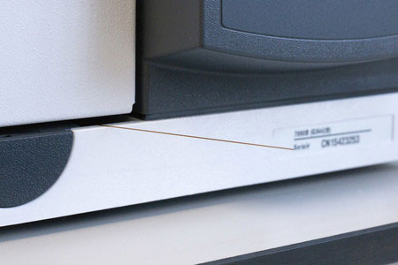
3. To condition the column using hydrogen carrier gas for GC-MS, carefully position the detector end of the column outside the GC oven and very carefully close the oven door, taking care not to break the column. You can see an example of this below:
4. Start the hydrogen flow through the capillary column to purge oxygen and other impurities from the column.
5. Check recommended heating programs and temperatures for the column which you have installed.
6. A general column conditioning guide from RESTEK can be found here
7. Once the column is conditioned, switch on the detector, connect the column, and allow at least 1hr stabilisation time.
System checkout
1. Once the column is conditioned, connect to the detector and allow at least 1h stabilisation time.
2. Check that all method setpoints are met by the system and are stable.
3. Run a blank sample to make sure that the detector baseline is stable.
4. Adjust the linear velocity of the carrier gas to match the value when using helium carrier gas. Running hydrogen at the same linear velocity as helium, with the same oven temperature program should give you almost identical results. Compare the last chromatogram using helium with the results with hydrogen. The peaks should elute at the same time, but may have a slightly different shape. This application note explains the process of switching carrier gas and keeping the linear velocity of the carrier gas the same.
5. Compare the reference chromatogram obtained using helium carrier gas with the new chromataogram to ensure that all peaks have eluted and that their retention times are consistent. If there is plenty of peak separation, you can carry out optimisation of the method to increase the linear velocity of the carrier gas and shorten run times. You may be able to halve the analysis time in some methods.
6. Ensure that you can identify all peaks in your mixture. Run calibration standards to revalidate the method.
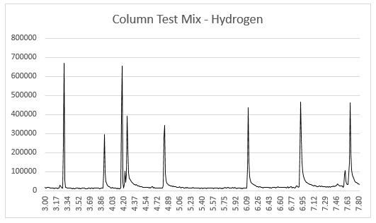 New Chromatogram
Found this article interesting? You might also like:
Cost-effective alternatives to helium for GC